What Is MTD in 3D Videoscope Measurement
Learn what MTD means in 3D videoscope measurement, why maximum target distance affects accuracy, and how inspectors can use MTD, point cloud view and verification methods to improve measurement reliability.
What Is MTD in 3D Videoscope Measurement?
In 3D videoscope measurement, many users focus on the final measurement value: the crack length, pit depth, missing area or clearance. However, a professional measurement result should not be judged by the number alone. The operator also needs to understand whether the measurement setup is reliable.
One important concept is MTD, which stands for Maximum Target Distance. MTD is a key indicator used in many 3D measurement workflows to help the inspector understand the distance relationship between the measurement tip and the measured feature.
Understanding MTD helps users make better decisions when measuring small pits, dents, cracks, welds, missing edges or other indications inside industrial components.
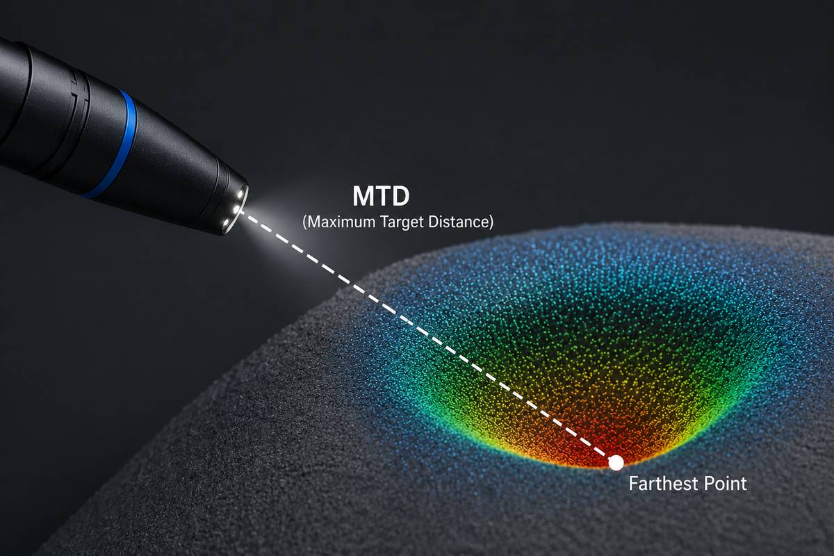
1. What Does MTD Mean?
MTD means Maximum Target Distance. In 3D videoscope measurement, it normally refers to the distance from the measurement tip to the cursor point that is farthest away from the tip within a given measurement.
This is important because a measurement may include several cursor points. For example, a depth measurement may use several reference points and one depth point. A point-to-line measurement may use two points to define a reference line and a third point to define the measured distance. Among all these cursor points, the one farthest from the probe tip determines the MTD value.
MTD is not the same as probe length. It is also not the same as field of view. It is a local measurement distance between the optical measurement tip and the measurement area.
2. Why MTD Matters
In most 3D measurement systems, accuracy is strongly affected by the distance between the probe tip and the target surface. When the probe is closer to the target, the defect usually occupies more pixels in the image, the 3D data becomes more detailed, and cursor placement becomes easier.
When the probe is too far away, several problems may occur:
The defect appears smaller in the image.
Surface details become less clear.
3D reconstruction may contain more noise.
Cursor placement becomes less repeatable.
Small depth or profile measurements become less reliable.
In general, a lower MTD often supports better measurement accuracy, especially for small defects. However, MTD is not the only factor. Surface condition, viewing angle, focus, lighting, calibration and operator technique also affect the final result.
3. MTD Is a Quality Indicator, Not a Guarantee
A low MTD does not automatically guarantee a perfect measurement, and a high MTD does not always mean the result is unusable. MTD should be understood as one important quality indicator within the complete measurement process.
For example, a relatively large length measurement on a clear, flat surface may still be acceptable at a larger MTD. But a very small pit depth or depth profile measurement may require a much lower MTD because the measured feature is small and easily affected by 3D data noise.
Therefore, the operator should not ask only: “What is the MTD value?” The better question is:
Is the MTD appropriate for this measurement type, this defect size and this surface condition?
4. Why Small Depth Measurements Need Lower MTD
Depth measurement is usually more sensitive than simple length measurement. A small depth value may be close to the noise level of the 3D data. If the probe is too far from the target, the 3D point cloud may not clearly distinguish the real defect shape from measurement noise.
This is especially important for:
Small corrosion pits.
Shallow dents.
Fine wear grooves.
Small weld height differences.
Depth profile measurements.
Area depth profile measurements.
For these cases, moving the probe closer can make the defect larger in the image and improve the amount of usable 3D surface information. The operator should also check the point cloud or depth map to confirm that the measured feature clearly stands out from the surrounding surface noise.
5. MTD and Point Cloud Noise
Point cloud noise refers to artifacts in the reconstructed 3D surface that do not represent the true geometry of the part. Noise may appear due to distance, reflection, surface texture, shadowing, poor viewing angle or unstable image capture.
MTD and point cloud noise are closely related. When the probe is too far from the surface, the system may have less detailed information to reconstruct the surface accurately. This can increase uncertainty in the measurement.
A professional workflow should use both MTD and point cloud review:
Check whether the MTD is reasonable for the measurement size.
Review the 3D point cloud to see whether the surface shape is stable.
Use the depth map to see whether the defect is clearly visible.
Avoid placing cursors on noisy or invalid data regions.
Repeat the capture from a closer distance or better angle if needed.
In many real inspections, problems that are difficult to see in the normal 2D image become more obvious in the 3D point cloud.
6. MTD and Different Measurement Modes
MTD affects different measurement modes in different ways. The following table summarizes typical considerations.
| Measurement Mode | How MTD Affects It | Practical Advice |
|---|---|---|
| Length | Often more tolerant of larger MTD if the feature is large and clear. | Move closer when measuring small cracks or short features. |
| Point to Line | Accuracy depends on correct placement of both the reference line and measured point. | Use lower MTD for small edge damage or narrow gaps. |
| Depth | Highly sensitive when the depth is small. | Move closer and check the point cloud or depth map. |
| Area | Cursor placement around the boundary becomes harder at larger MTD. | Use zoom and verify the boundary in the 3D view. |
| Multi-Segment | Longer paths may tolerate larger MTD, but small irregular details need closer viewing. | Place cursors along the actual defect path and avoid noisy points. |
| Depth Profile | Very sensitive when measuring small surface height or depth changes. | Use low MTD and confirm that the profile is larger than data noise. |
| Area Depth Profile | Needs reliable surface data across a wider area. | Use suitable distance, stable capture and correct reference surface. |
| Measurement Plane | MTD still matters because the plane depends on the quality of the reference surface data. | Use a clear, undamaged reference surface and check plane alignment. |
7. MTD and Viewing Angle
MTD alone does not describe the complete measurement setup. Viewing angle is also important. A low MTD with a poor viewing angle may still produce unreliable results.
For example, when measuring a rounded edge, missing corner or blade edge damage, the viewing perspective can affect how the cursor positions relate to the actual 3D surface. In such cases, the operator should not rely only on the 2D image. The point cloud, surface mask or other quality indicators should be used to confirm that the measurement geometry is correct.
In practical terms, the operator should consider both:
Distance: Is the probe close enough to the target?
Angle: Is the surface viewed from a suitable direction for this measurement?
8. MTD and Surface Reflection
Reflective, oily or wet surfaces can reduce 3D data quality. Even if the MTD appears acceptable, strong reflection may create noisy, missing or low-quality 3D data. This is why a measurement should be checked visually in the point cloud or depth map whenever possible.
To improve the measurement setup, the operator can try:
Changing the viewing angle.
Reducing glare with lighting adjustment.
Moving slightly closer or farther to improve image quality.
Using image enhancement only when it helps cursor placement without hiding surface detail.
Taking another capture from a better orientation.
The goal is not only to reduce MTD, but to obtain a clean and useful 3D surface reconstruction.
9. MTD and Focus
For stereo-based systems, the area of interest usually needs to be in sharp focus. If the image is blurred, the software may have difficulty matching surface points, and the operator may place cursors inaccurately.
For structured-light systems, the relationship between focus, distance and accuracy can depend on the optical design. However, the same general rule still applies: the operator must make sure the defect area is large enough, clear enough and stable enough for reliable measurement.
A zoom window or magnified cursor placement tool can be helpful, especially when measuring small features.
10. How to Use MTD During Inspection
MTD should be used as part of a practical inspection workflow.
Locate the indication. Find the crack, pit, dent, edge damage or other defect.
Move to a suitable distance. Bring the probe close enough to make the defect large and clear in the image.
Adjust the viewing angle. Reduce glare and choose an angle that supports the intended measurement.
Capture the 3D measurement image. Keep the probe as stable as possible during capture.
Review MTD. Check whether the distance is suitable for the measurement size and type.
Review the point cloud or depth map. Confirm that the defect is clearly represented in 3D data.
Place cursors carefully. Use zoom or surface guidance tools if available.
Repeat if needed. If MTD is too high, data is noisy or the feature is unclear, capture again from a better position.
11. Common Mistakes Related to MTD
Many measurement errors are caused by misunderstanding distance and scale. Common mistakes include:
Measuring from too far away because the defect is visible but not large enough for reliable measurement.
Assuming that a sharp-looking 2D image always means the 3D data is accurate.
Using one MTD rule for all measurement types.
Measuring small depth features without checking point cloud noise.
Ignoring system warnings related to distance or measurement size.
Comparing measurement results without considering whether the MTD was the same.
Using a screenshot as evidence without saving re-measurable measurement data.
Good measurement practice requires the operator to consider distance, geometry, surface condition and measurement mode together.
12. How to Verify MTD-Related Measurement Reliability
Before using 3D measurement for important decisions, users should verify how the system behaves at different distances. This can be done with a known reference block or a sample part with known dimensions.
A simple verification process may include:
Measure the same known feature at several distances.
Record the MTD value for each measurement.
Compare the measured result with the known value.
Repeat the measurement several times to check repeatability.
Try different viewing angles to see how the result changes.
Check whether small depth measurements become less stable at larger MTD.
Confirm whether the system provides warnings when the setup is not suitable.
This type of practical verification helps users understand the real working range of their measurement system instead of relying only on a single advertised accuracy value.
13. What Should Be Included in a 3D Measurement Report?
A useful measurement report should include more than only the final number. For better traceability, it is helpful to include:
Measurement image.
Measurement mode used.
Measurement result and unit.
MTD value or measurement distance information if available.
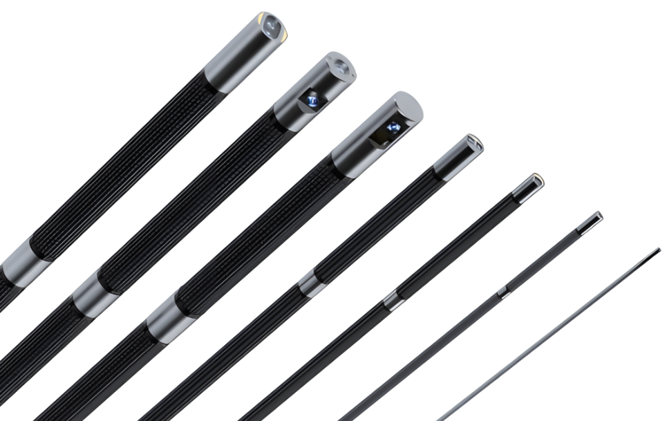
Probe and measurement tip information.
Operator name and inspection date.
Part location or inspection point.
Comments on surface condition or measurement difficulty.
Whether the measurement was verified with a reference block.
Whether the original data can be reopened and re-measured.
For critical inspection work, traceability and repeatability are often as important as the first measurement result.
14. Practical Summary
MTD is one of the most useful concepts for understanding 3D videoscope measurement reliability. It tells the operator how far the farthest measurement cursor is from the probe tip. In general, lower MTD supports better accuracy, especially for small depth and profile measurements.
However, MTD should never be used alone. A reliable measurement also depends on point cloud quality, viewing angle, surface condition, focus, calibration, cursor placement and operator training.
The best practice is simple: move close enough, choose a suitable angle, review the 3D data, watch for warnings, and verify the result when the measurement is important.
By understanding MTD, users can better judge whether a 3D measurement result is reliable, repeatable and suitable for the inspection decision they need to make.
FAQ: MTD in 3D Videoscope Measurement
What does MTD stand for?
MTD stands for Maximum Target Distance. It usually refers to the distance from the measurement tip to the cursor point that is farthest from the tip in a given measurement.
Is lower MTD always better?
Lower MTD often improves measurement accuracy, especially for small features. However, the image must still be clear, the viewing angle must be suitable, and the 3D data must be reliable.
Why is MTD important for depth measurement?
Small depth measurements are sensitive to 3D data noise. If the probe is too far away, the measured depth may be close to the noise level of the point cloud, reducing reliability.
Can a large feature be measured at a higher MTD?
Sometimes yes. Large length measurements may tolerate larger MTD values better than very small depth or profile measurements. The operator should still review the 3D data quality.
Is MTD the same as probe length?
No. Probe length is the physical length of the insertion tube. MTD is the local measurement distance between the measurement tip and the farthest measurement cursor point.
Does MTD guarantee measurement accuracy?
No. MTD is only one quality indicator. Accuracy also depends on calibration, surface condition, viewing angle, focus, point cloud noise and cursor placement.
How can I reduce MTD?
Move the probe tip closer to the target surface while keeping the area of interest visible and suitable for measurement. Make sure the image remains usable and the probe is stable during capture.
What should I do if the MTD is too high?
Try to move closer, adjust the viewing angle, reduce glare and capture the measurement image again. If the defect cannot be approached, consider whether the measurement result is reliable enough for the inspection decision.
Why do repeated measurements give different results?
Different MTD values, viewing angles, cursor positions, surface reflections or point cloud noise can change the result. Repeatability should be checked when measurement accuracy is important.
Should MTD be included in inspection reports?
For important measurements, including MTD or distance-related information can improve traceability and help reviewers understand the measurement conditions.