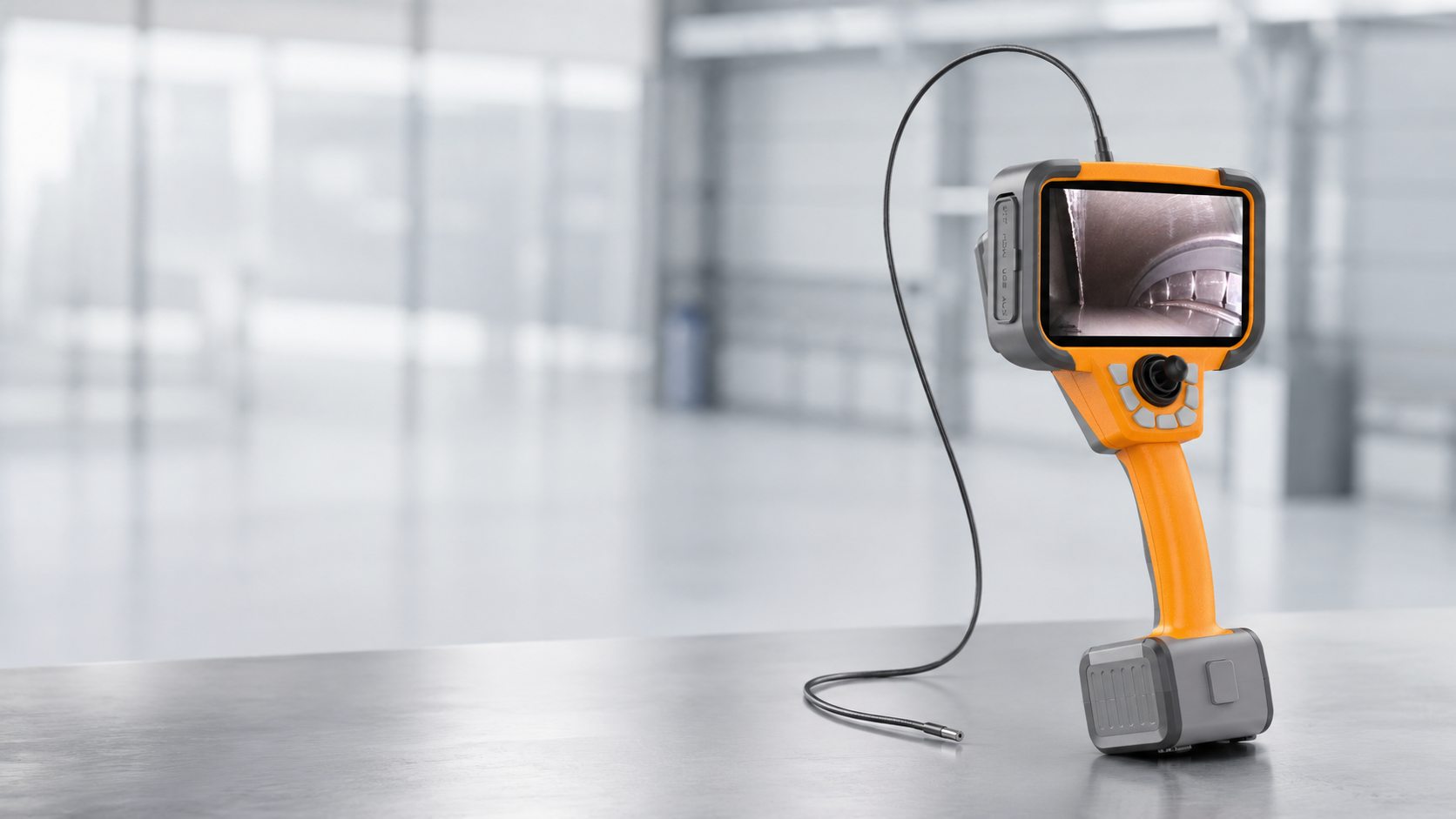
Understanding 3D Measurement in Industrial Videoscopes Technologies Measurement Modes and Accuracy Control
Learn how 3D measurement in industrial videoscopes works, including structured light, stereo optics, dual-camera systems, measurement modes, accuracy factors and practical verification methods.
Understanding 3D Measurement in Industrial Videoscopes: Technologies, Measurement Modes and Accuracy Control
3D measurement has become one of the most discussed features in modern industrial videoscopes. Many systems today promote terms such as 3D measurement, point cloud, AI-assisted inspection, virtual plane, depth profile and automatic defect measurement. These terms can be useful, but they can also be misleading if they are understood only as marketing language.
The real value of 3D measurement is not simply that the instrument can display a number on the screen. In professional industrial inspection, the more important question is: how reliable is that number, and can the measurement be verified?
This article explains the main technical principles behind 3D videoscope measurement, common measurement modes, typical defect applications, and practical methods for controlling measurement accuracy. The goal is to help inspectors, engineers and purchasing teams better understand the terminology and evaluate 3D measurement claims more objectively.
1. What Does 3D Measurement Mean in a Videoscope?
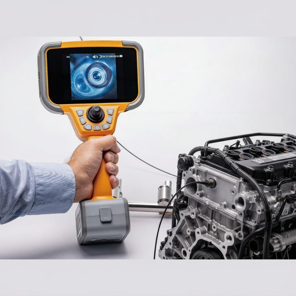
A normal videoscope image is a two-dimensional view of the inspection area. The operator can see a crack, pit, dent, missing edge, corrosion mark or surface damage, but a 2D image alone does not provide reliable depth or spatial information.
A 3D measurement videoscope attempts to reconstruct the surface geometry of the inspected area. This allows the operator to measure not only length and width, but also depth, height, surface area, profile shape, missing material and clearance.
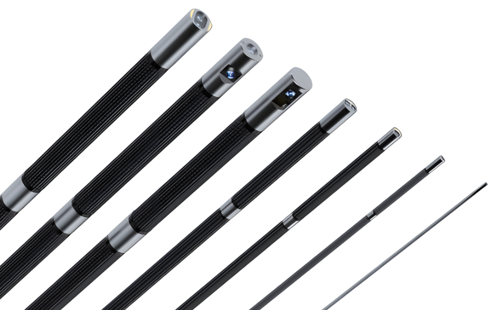
A practical 3D measurement system usually includes three parts:
3D data acquisition: the system collects depth or surface geometry information.
Measurement software: the operator selects measurement modes, places cursors and calculates results.
Measurement quality control: the system helps the operator judge whether the data and cursor placement are reliable.
A measurement result without quality feedback can be misleading. A professional system should help the user understand not only what the measured value is, but also whether the result can be trusted under the current inspection conditions.
2. Main Technologies Used for 3D Videoscope Measurement
2.1 Structured Light / Phase-Based 3D Measurement
Structured light measurement uses a measurement tip or optical module to project a known light pattern onto the target surface. The camera captures how the projected pattern changes across the surface, and the software calculates the 3D geometry from the deformation of the pattern.
This method can generate detailed 3D surface data and is especially useful for measuring pits, dents, corrosion, missing edges, blade damage, weld height and surface profiles.
Advantages:
Can generate dense 3D surface data.
Useful for depth, profile, area and complex surface measurements.
Can support advanced tools such as measurement plane, depth profile and area depth profile.
Limitations:
Requires stable image capture.
Reflective, oily or shadowed surfaces may reduce 3D data quality.
Measurement accuracy depends strongly on tip-to-target distance, surface condition and viewing angle.
2.2 Stereo Measurement with Dual Optical Paths
Stereo measurement uses two slightly different perspectives of the same target. This can be achieved by a special stereo optical tip, a prism-based optical design, or two optical paths inside one measurement adapter. The software compares corresponding points in the two images and calculates 3D coordinates by triangulation.
Traditional stereo measurement requires careful cursor placement and correct matching between the two views. More advanced stereo systems may also generate a 3D point cloud to help the operator review the surface geometry.
Advantages:
Can work well on surfaces with enough visual texture.
May perform well on some reflective or oily surfaces where projected light patterns are difficult to read.
Can be suitable for length, point-to-line, depth and area measurements.
Limitations:
Matching errors between the two views can affect accuracy.
Repeated patterns, glare or low surface texture can make matching difficult.
Operator training is important, especially for cursor placement.
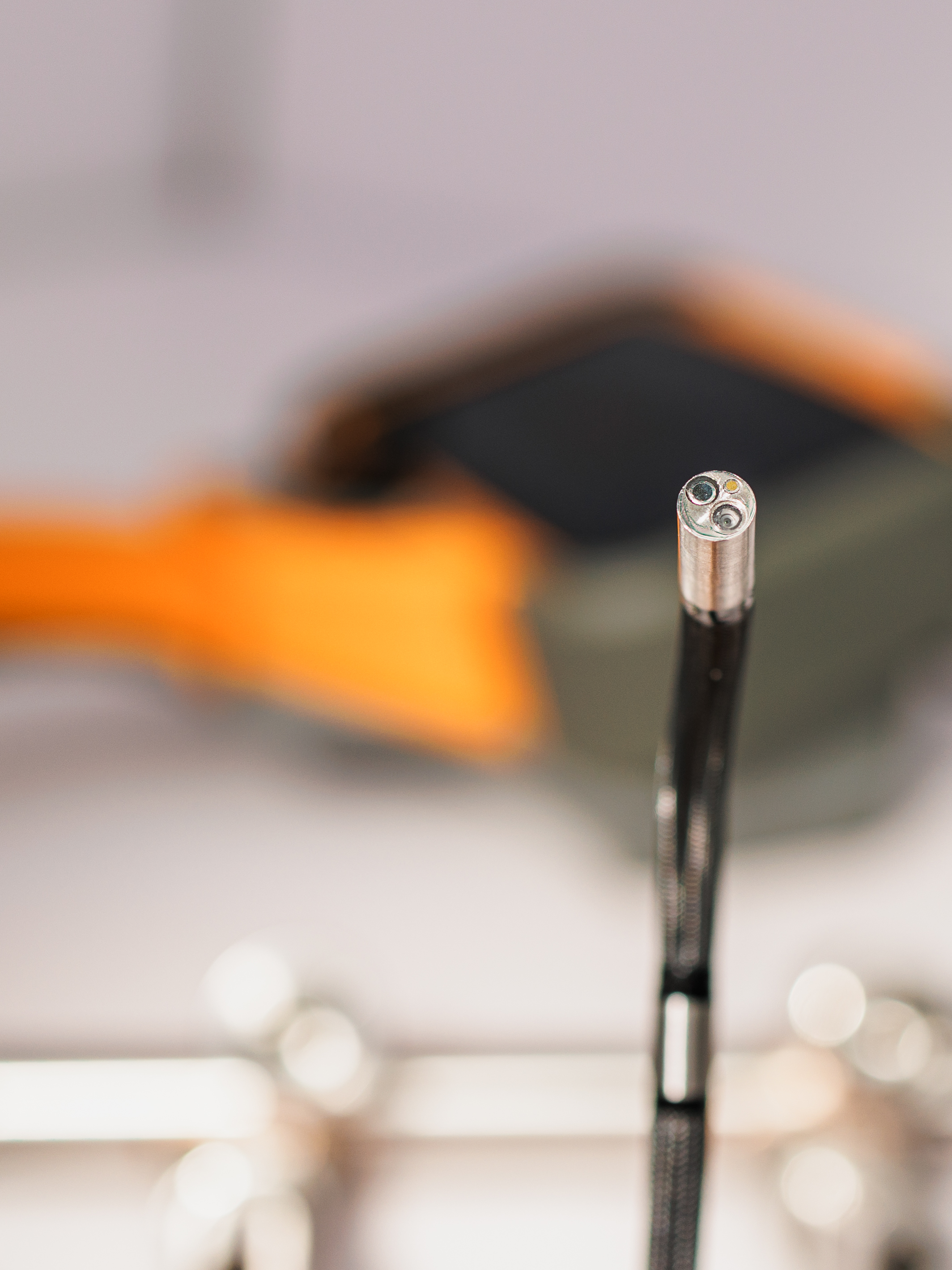
2.3 Dual-Camera 3D Measurement
Some videoscopes use two camera sensors at the probe tip to create a stereo view. The two cameras capture the target from slightly different angles, and the software reconstructs depth information from the difference between the two images.
This approach is conceptually similar to stereo vision used in robotics and machine vision. Depending on the probe design, a dual-camera 3D videoscope may support front-view measurement, side-view measurement or both.
Advantages:
Clear hardware concept with two image sources.
Can be useful for practical industrial measurement tasks.
May support point cloud or 3D model visualization.
Limitations:
The distance between the two cameras is very small in a videoscope probe, which limits measurement range and accuracy.
Calibration stability is critical.
Performance depends on image quality, lighting, surface texture and software processing.
2.4 Laser Line or Laser Spot Measurement
Some systems project a laser line, laser dot or laser pattern onto the inspection surface. The camera observes the position or deformation of the laser projection, and the software calculates distance, profile or surface geometry.
Laser-based approaches can be effective for certain distance or profile measurements, but they may also be affected by reflectivity, surface color, viewing angle and access limitations.
2.5 Comparison Measurement and Reference Measurement
Comparison measurement is not true 3D reconstruction. It uses a known reference size in the image to estimate another dimension. For example, if a reference target of known size is visible at the same distance as the defect, the software can calculate approximate dimensions in the 2D image.
This method can be useful for basic documentation, but it is highly dependent on correct reference placement. If the defect and the reference are not on the same plane or at the same distance from the camera, the result can be inaccurate.
3. Common Measurement Modes and Their Practical Meaning
Different measurement modes are designed for different defect types. A professional operator should not only know the name of the mode, but also understand when it is appropriate to use it.
| Measurement Mode | What It Measures | Typical Applications |
|---|---|---|
| Length | Straight-line distance between two selected points | Crack length, component size, wear mark length |
| Point to Line | Perpendicular distance from a point to a reference line | Edge damage, gap width, missing edge estimation, weld width |
| Depth | Distance from a reference plane to a point above or below that plane | Pit depth, dent depth, weld height, blade clearance |
| Area | Surface area enclosed by multiple cursor points | Coating loss, missing material, corrosion area, FOD damage |
| Multi-Segment | Total length along a curved or irregular path | Curved cracks, irregular edge damage, blended areas |
| Depth Profile | Cross-section depth or height along a selected line | Pit profile, weld height, wear groove, impact damage |
| Area Depth Profile | Maximum height or depth within a defined area | Pitting field, corrosion field, erosion, maximum groove depth |
| Measurement Plane / Virtual Plane | A reference plane used together with other measurement modes | Missing corners, edge damage, blade tip clearance, flat surface reference |
| Radius / Angle / Surface Angle | Geometric shape or angular relationship | Radius damage, corner deformation, surface orientation |
4. Measurement Plane: More Than a Simple Measuring Tool
A measurement plane, sometimes called a virtual plane, is one of the most important concepts in advanced 3D measurement. It is not simply another measurement mode. It is a reference layer that can be used together with other measurement modes.
For example, if a blade corner is missing, the original corner no longer physically exists. A simple point-to-point measurement cannot directly measure the missing original shape. A measurement plane can mathematically extend the remaining surface, allowing the software to estimate missing area, missing edge length or clearance in a more meaningful way.
Measurement plane is useful when:
3D data is missing near an edge.
The defect is located in a noisy or low-quality 3D data region.
The operator needs to measure a missing corner or missing edge.
The defect should be measured relative to an original flat surface.
The surface contains pits, but the reference surface should remain flat.
However, measurement plane must be used carefully. If the reference plane is placed on a curved, damaged or incorrect surface, the result may be misleading. A good system should provide visual feedback to help the user verify that the reference plane is correctly aligned with the surface.
5. Depth Profile and Area Depth Profile
5.1 Depth Profile
Depth profile measures the height or depth variation along a selected line. Instead of giving only one point depth, it shows the surface contour across a slice. This is useful for understanding the shape of a pit, weld, groove or impact mark.
Typical applications include:
Depth of isolated corrosion pits.
Depth of FOD impact damage.
Weld height or wear groove depth.
Quick assessment of surface contour.
5.2 Area Depth Profile
Area depth profile extends this idea from one line to a defined area. The software analyzes multiple profile slices within the selected area and identifies the maximum depth or maximum height.
This is especially useful for:
Corrosion fields.
Pitting clusters.
Erosion damage.
Maximum weld height.
Maximum wear groove depth.
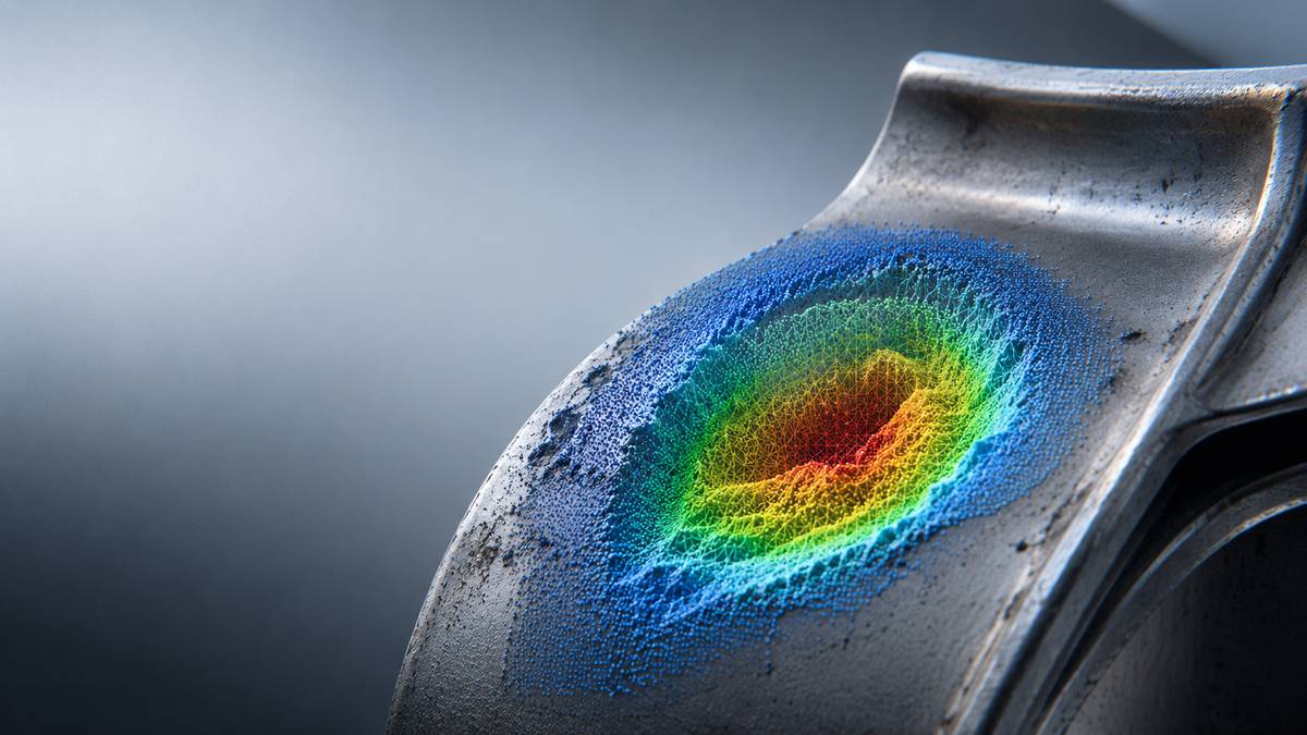
For many real industrial defects, the deepest point is not always obvious in a normal image. A depth map, point cloud or area profile function can help the operator confirm whether the selected measurement truly captures the most critical area.
6. Accuracy vs. Resolution: A Common Misunderstanding
In marketing materials, users may see statements such as “0.01 mm resolution” or “high accuracy measurement.” It is important to understand the difference between resolution and accuracy.
Resolution refers to the smallest display increment or numerical step the software can show.
Accuracy refers to how close the measured result is to the true value.
Precision refers to how repeatable the measurement is when repeated under the same conditions.
A system may display results in 0.01 mm increments, but that does not mean the real measurement accuracy is 0.01 mm. Real accuracy depends on calibration, camera position, distance, surface condition, lighting, 3D data quality and operator technique.
7. Key Factors That Affect 3D Measurement Accuracy
7.1 Tip-to-Target Distance
The distance between the probe tip and the target is one of the most important factors in 3D measurement. In general, a closer distance provides more image detail and better 3D data quality, as long as the target remains within the working distance of the optical system.
If the probe is too far from the target, the defect occupies fewer pixels, the 3D surface becomes less detailed, and small depth measurements become less reliable.
7.2 Viewing Angle
The angle between the camera and the target surface affects the quality of 3D reconstruction. For some depth measurements, a slightly off-perpendicular view may be better than a perfectly straight view, especially on shiny surfaces. For edge measurements, viewing perspective can strongly influence accuracy.
When measuring near a rounded edge or missing edge, the operator should verify that the viewing angle supports the intended measurement direction.
7.3 Surface Condition
Reflective, oily, wet, dark, dirty or highly textured surfaces can affect 3D measurement. Structured light patterns may be distorted by reflection or shadowing. Stereo systems may struggle if the surface has too little texture or too much repeated texture.
Before measuring, the operator should adjust brightness, reduce glare where possible, and choose a viewing orientation that gives better surface information.
7.4 Focus and Image Sharpness
Cursor placement depends on image clarity. If the image is blurred, the operator may place cursors at the wrong location. For small defects, a zoom window or magnified cursor placement view can significantly improve repeatability.
7.5 Calibration and Verification
3D measurement systems rely on calibrated optical geometry. If the measurement tip, probe head or camera system is not properly calibrated, the result may be wrong even if the software interface appears normal.
Professional users should verify measurement performance with a known reference block before and after critical inspections. This does not guarantee every field measurement, but it helps confirm that the equipment is functioning correctly.
7.6 Operator Technique
3D videoscope measurement is not fully automatic. The operator must select the correct mode, place cursors correctly, review the 3D data and decide whether the result is acceptable. Training remains essential.
8. Useful Quality Indicators in a Professional 3D Measurement System
A professional measurement system should provide tools to help the user evaluate measurement confidence. These tools may include:
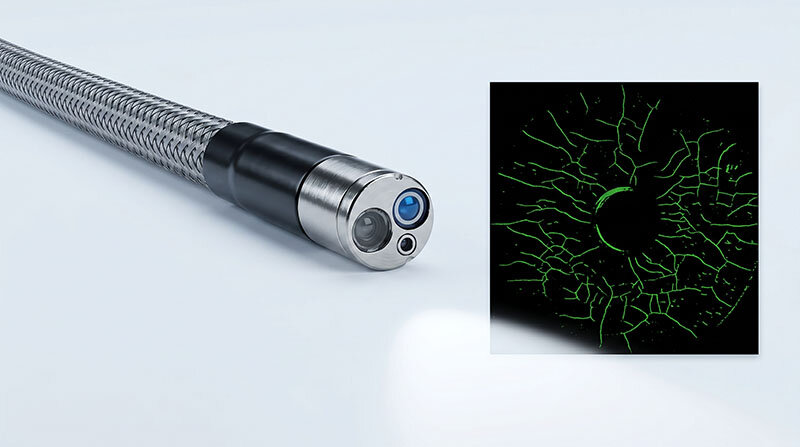
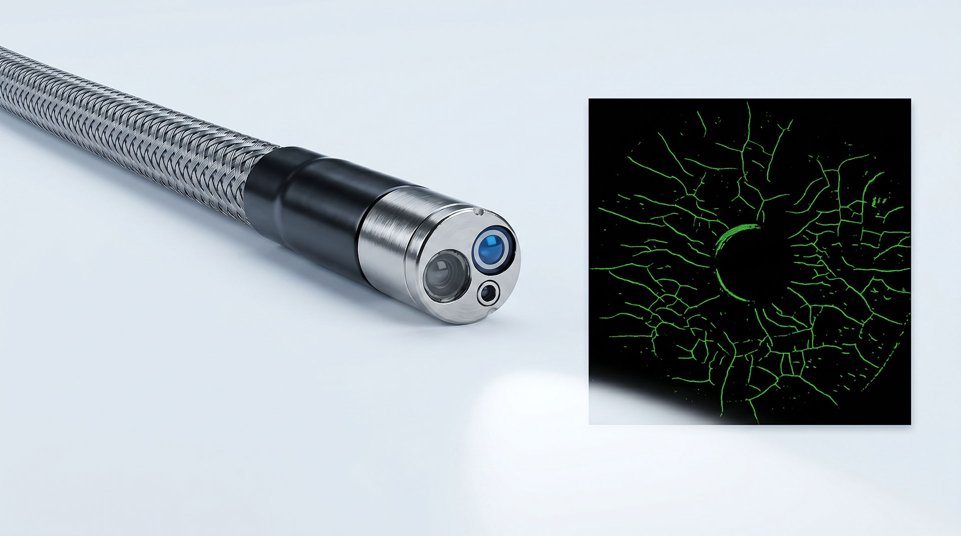
Point cloud view: allows the user to rotate and inspect the reconstructed surface.
Depth map: helps visualize high and low areas on the surface.
Invalid data mask: shows areas where the system could not calculate reliable 3D data.
Low-quality data warning: highlights regions affected by reflection, shadow or noise.
Surface mask: helps guide correct cursor placement on the reference surface.
Tip-to-target distance indicator: helps the user understand whether the target is too far away.
Measurement warnings: alerts the operator when the setup may not support reliable measurement.
Re-measurement capability: allows saved data to be reopened and measured again, instead of saving only a flattened screenshot.
When evaluating a 3D videoscope, customers should not only ask whether the system can measure. They should ask how the system helps verify that the measurement is meaningful.
9. Matching Measurement Modes to Defect Types
Choosing the correct measurement mode is just as important as having the measurement feature itself.
| Defect Type | Recommended Measurement Approach | Notes |
|---|---|---|
| Simple crack | Length | Use when the crack path is relatively straight. |
| Curved or branching crack | Multi-Segment | Follows irregular crack paths more accurately than straight length. |
| Pit or dent | Depth or Depth Profile | Use point cloud or depth map to confirm the deepest point. |
| Corrosion or pitting field | Area Depth Profile | Useful for finding maximum depth within an area. |
| Missing corner | Measurement Plane + Area | Requires careful reference plane placement. |
| Blade edge damage | Measurement Plane + Point to Line | Useful when edge data is missing or noisy. |
| Wear groove | Depth Profile or Area Depth Profile | Profile view helps understand groove shape. |
| Weld height | Depth or Depth Profile | Reference surface selection is critical. |
| Gap or clearance | Point to Line or Depth | Mode depends on geometry and viewing direction. |
| Coating loss | Area | Depth may be added if material loss thickness is visible and measurable. |
10. AI-Assisted Defect Recognition and 3D Measurement
AI-assisted videoscope inspection is often discussed together with 3D measurement, but they are different functions.
AI can help detect, classify or highlight possible indications such as cracks, dents, erosion, deposits or coating loss. However, AI detection is not the same as measurement. A good workflow should separate these steps:
AI detects a possible indication.
The operator reviews the AI result.
The operator accepts, rejects or edits the indication.
The operator selects the correct measurement mode.
The system performs 2D or 3D measurement.
The result is saved with inspection metadata and operator comments.
AI should support the inspector, not replace the inspector. For critical inspections, the final responsibility remains with the qualified operator and the applicable inspection procedure.
11. How to Verify a 3D Measurement System Before Purchase
Customers can avoid misunderstanding by asking practical verification questions before purchasing a 3D measurement videoscope.
11.1 Technical Questions
What 3D measurement technology is used: structured light, stereo optics, dual camera, laser or comparison measurement?
Does the system generate a real 3D point cloud?
Can the point cloud be viewed, rotated or exported?
Does the system provide a depth map or surface quality mask?
Does the system show invalid or low-quality 3D data regions?
Can saved measurement images be reopened and re-measured?
Does the system store measurement metadata, or only a screenshot?
11.2 Accuracy Questions
What is the stated accuracy at different tip-to-target distances?
Is the accuracy tested on flat surfaces only, or also on edges, pits, curved surfaces and reflective surfaces?
Is there a verification block or calibration target?
Can the user verify the system before and after inspection?
Are measurement results repeatable between different operators?
Does the system provide accuracy data for different measurement modes?
11.3 Application Questions
Can the system measure the specific defect type you need?
Can it measure missing corners or only visible points?
Can it measure maximum pit depth within a corrosion field?
Can it measure edge damage where 3D data may be missing?
Can it support the required probe diameter, viewing direction and access condition?
Does the measurement mode match the actual inspection geometry?
12. A Practical Demonstration Checklist
When watching a demonstration, do not only look at the final measurement number. Ask the demonstrator to show the complete workflow:
Capture the 3D image.
Show the point cloud.
Show the depth map or surface mask.
Show the measurement distance or quality indicator.
Measure a simple feature.
Measure a pit or dent.
Measure an edge or missing corner if the system supports it.
Save the file.
Reopen the file and move the cursors again.
Generate a report with measurement data.
If the system can only show a measurement overlay on a saved image, but cannot preserve the underlying measurement data, it may be sufficient for basic documentation but may not be suitable for critical measurement decisions.
13. What Customers Should Be Careful About
3D measurement is a useful technology, but customers should be cautious when evaluating broad claims. The following statements require careful interpretation:
“0.01 mm resolution” does not automatically mean 0.01 mm real-world accuracy.
“AI defect detection” does not mean the system will find every defect.
“Point cloud” does not guarantee that the measurement data is accurate under all conditions.
“Automatic measurement” still requires correct inspection setup and operator review.
“3D measurement accuracy” should be supported by test conditions, distance range and verification method.
A reliable supplier should be able to explain not only what the system can do, but also where its limitations are.
14. Final Thoughts
3D measurement can be a powerful tool in industrial videoscope inspection, but it should be understood as a complete measurement process, not only as a feature name. The most important question is not whether a system can display a measurement value. The more important question is whether the system provides enough data, guidance and verification tools to support a reliable decision.
A professional user should understand the measurement technology, choose the correct measurement mode, control distance and viewing angle, verify calibration, review the 3D data, and document the result properly. With this knowledge, customers can evaluate 3D measurement claims more objectively and select a system that matches their real inspection needs.
FAQ: 3D Measurement in Industrial Videoscopes
Is 3D measurement always more accurate than 2D measurement?
Not always. 3D measurement can provide more meaningful spatial information, but accuracy depends on calibration, distance, surface condition, viewing angle, image quality and operator technique.
Does 0.01 mm resolution mean 0.01 mm accuracy?
No. Resolution is the smallest displayed numerical step. Accuracy is how close the result is to the true value. A system may display 0.01 mm increments without achieving 0.01 mm real-world accuracy.
What is a point cloud?
A point cloud is a 3D representation of the measured surface made of many calculated points. It helps the operator understand surface shape, defect depth and cursor placement.
What is a measurement plane?
A measurement plane is a reference plane used together with other measurement modes. It can help measure missing corners, edge damage or defects where some 3D data is missing or noisy.
What is the difference between depth and depth profile?
Depth usually measures the distance from a reference plane to one selected point. Depth profile shows the height or depth variation along a line, which helps the operator understand the shape of the defect.
What is area depth profile used for?
Area depth profile is used to find maximum height or depth within a selected area. It is useful for corrosion fields, pitting clusters, erosion and wear grooves.
Can AI measure defects automatically?
AI can help detect or classify possible indications, but measurement should still be verified by the operator. AI detection and 3D measurement are related but separate steps.
How can I verify a 3D measurement videoscope?
Use a known reference block, check results at different distances, repeat the measurement, compare different operators, review the point cloud, and confirm whether saved data can be reopened and re-measured.
Why does tip-to-target distance matter?
If the probe is too far from the target, the defect occupies fewer pixels and the 3D data becomes less detailed. This can reduce measurement accuracy, especially for small depth measurements.
What should I ask before buying a 3D measurement videoscope?
Ask what 3D technology is used, whether the system generates a real point cloud, whether accuracy is verified at different distances, whether the system provides quality warnings, and whether saved files can be re-measured.