Ultra-Thin Videoscope Probes for Aerospace and Precision Medical Device Inspection
Learn how ultra-thin videoscope probes inspect turbine blade cooling passages, aerospace castings, pacemaker components, catheters, cannulas and miniature precision tubes.
Ultra-Thin Videoscope Probes for Aerospace and Precision Medical Device Inspection
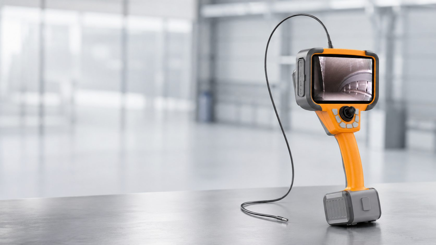
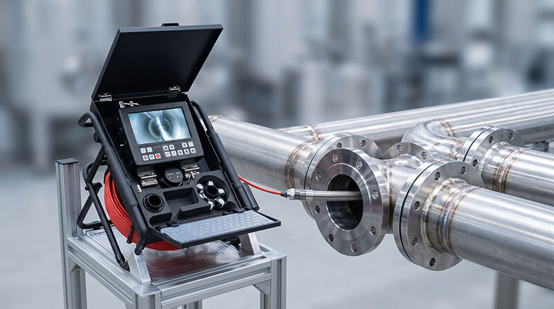
Ultra-thin videoscope probes provide direct visual access to internal passages, micro-holes and precision cavities that cannot be reached by conventional 4 mm or 6 mm industrial videoscopes.
In high-value manufacturing, the inspection target may be an internal cooling passage inside an aircraft turbine blade, a laser-drilled film-cooling hole, a miniature tube in a medical device or an internal component of a pacemaker before final assembly.
These applications are fundamentally different from general machinery inspection. The access opening may be less than 1 mm, the working distance may be only a few millimetres and the inspected component may have a very high manufacturing value.
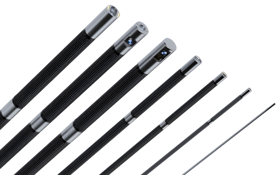
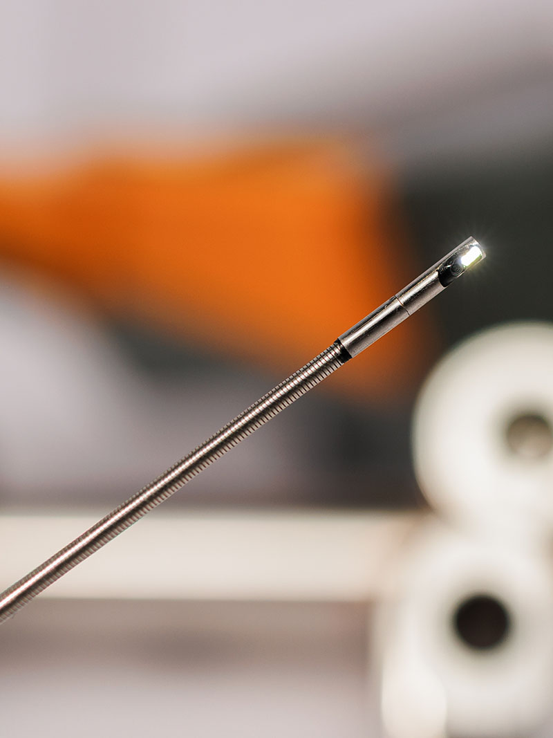
The latest ultra-thin electronic videoscope technology can provide probe diameters down to approximately 0.7 mm, depending on the required probe length, optical configuration, illumination method and mechanical construction.
Probe diameter is important, but image quality, illumination, insertion stiffness, depth of field, viewing direction and repeatable positioning are equally critical.
Key Selection Principle
The smallest available probe is not automatically the best probe.
A 0.7 mm, 0.95 mm or 1.0 mm probe may be necessary for a very small cooling hole or miniature tube. However, a 1.6 mm, 1.8 mm or 2.0 mm probe will normally provide better illumination, greater mechanical stability and easier handling when the access opening allows it.
The correct configuration should be selected according to the complete inspection path, not only the nominal diameter of the entrance hole.
What Is an Ultra-Thin Videoscope Probe?
There is no universal industry definition that fixes one exact diameter for the term ultra-thin videoscope.
In practical industrial use, the term normally refers to electronic inspection probes designed for access openings significantly smaller than those used by conventional industrial videoscopes.
Current ultra-thin electronic videoscope configurations may include probe diameters such as:
0.7 mm
0.95 mm
1.0 mm
1.2 mm
1.6 mm
1.8 mm
2.0 mm
2.4 mm
2.8 mm
The exact available diameter depends on the required length, sensor design, illumination method, viewing direction and probe construction.
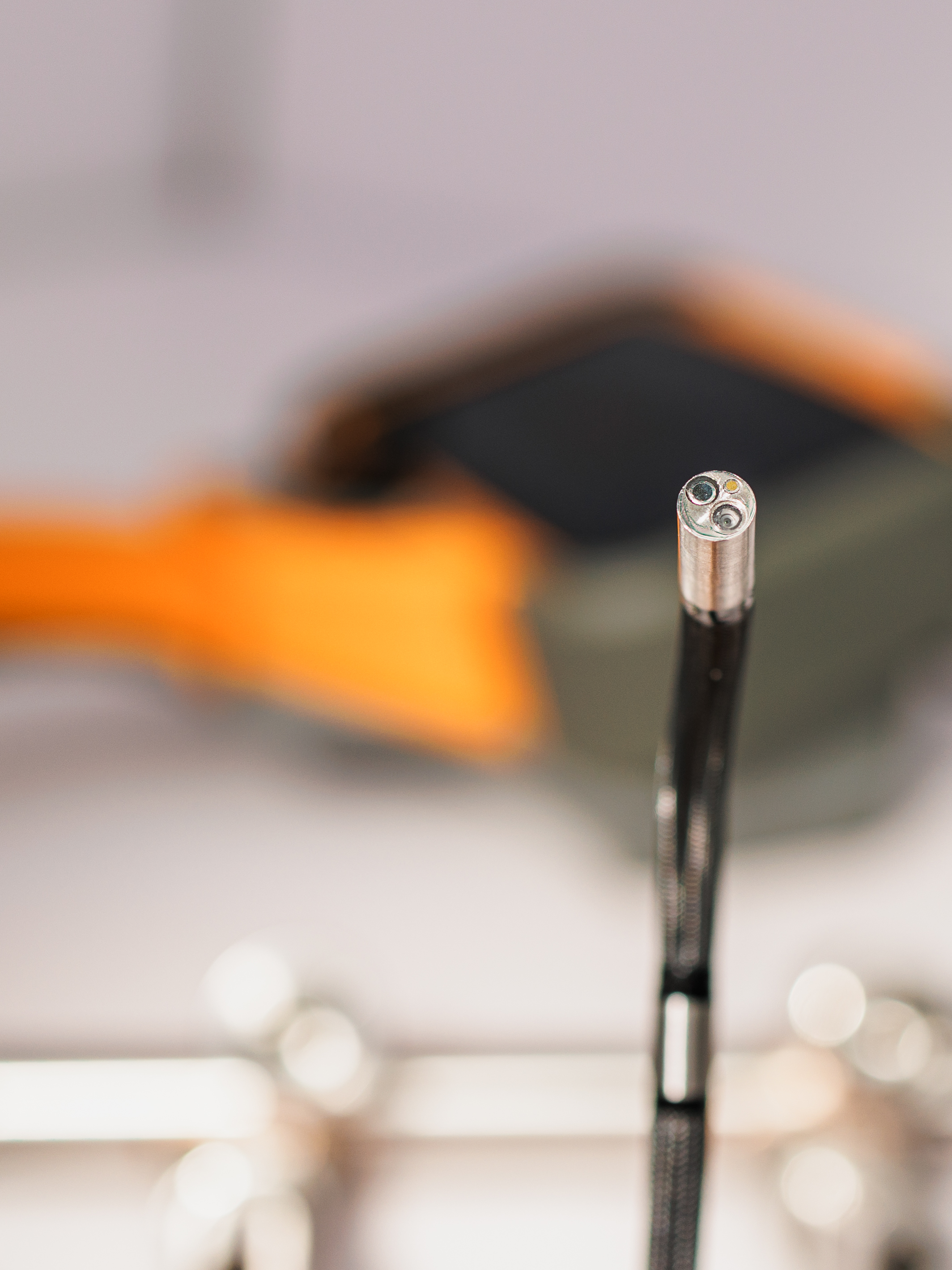
At these dimensions, the probe must accommodate the camera sensor, optical lens, illumination path, signal conductors and protective outer sheath within an extremely small cross-section.
As probe diameter decreases, possible compromises include:
Lower illumination output
Smaller image sensor
Reduced mechanical strength
Limited or no articulation
More difficult insertion control
Greater sensitivity to repeated bending
Reduced practical working length
Ultra-thin probes should therefore be treated as specialised precision inspection instruments rather than simply smaller versions of a standard industrial videoscope.
Why Ultra-Thin Inspection Is Used in High-Value Manufacturing
Aerospace and medical components often contain internal features that are essential to performance but cannot be examined directly after machining, casting, drilling, welding or assembly.
Opening or sectioning the component would destroy it. Computed tomography, radiography and other advanced inspection methods may provide additional information, but they may require specialised equipment, longer inspection cycles or separate interpretation.
An ultra-thin videoscope can provide immediate visual confirmation of accessible internal surfaces without cutting or destroying the component.
Typical inspection objectives include:
Confirming that an internal passage is open
Locating residual material or foreign objects
Checking drilled-hole breakthrough
Identifying burrs or sharp edges
Observing visible casting defects
Checking internal surface condition
Verifying assembly position
Documenting damage before further processing
Investigating rejected flow-test results
Supporting root-cause analysis
In these applications, the videoscope is generally used as part of a controlled manufacturing or quality-assurance process. Acceptance criteria should be defined by the component manufacturer rather than based only on a general visual impression.
Aerospace and Aviation Manufacturing Applications
Modern aerospace components use complex internal geometries to reduce weight, control temperature and improve aerodynamic or fluid performance.
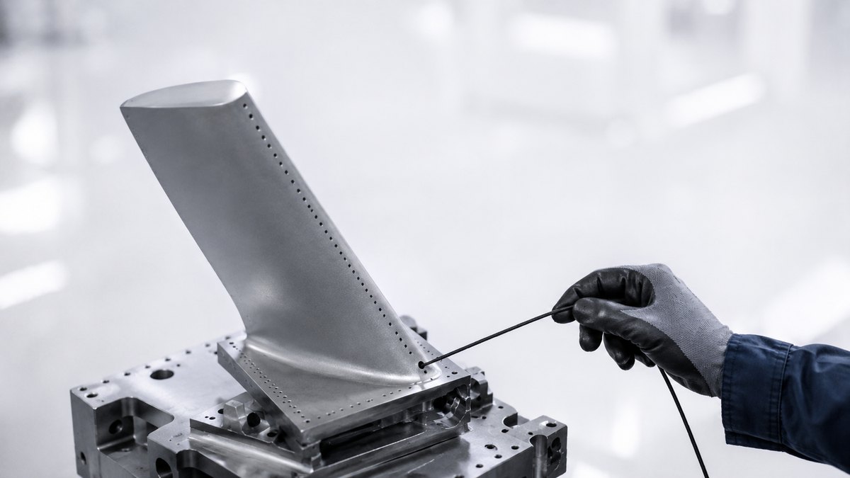
High-pressure turbine blades and vanes can contain complex internal air passages and precisely manufactured external cooling holes. These internal structures allow cooling air to flow through the component and protect the blade during high-temperature operation.
Ultra-thin videoscope probes may be used during the manufacture or investigation of:
Turbine blades and vanes
Investment-cast airfoils
Internal cooling passages
Film-cooling holes
Trailing-edge discharge openings
Fuel nozzles and injector components
Miniature manifolds
Precision aerospace tubes
Small hydraulic or pneumatic passages
Additively manufactured aerospace components
Sensor housings
Small machined bores
Cross-drilled precision components
Turbine Blade Casting and Internal Cooling-Passage Inspection
Many turbine blades and vanes are manufactured by investment casting. Internal cavities are formed using complex cores that create cooling passages inside the final airfoil.
After casting and core removal, the internal geometry may need to be examined for defects, blockage or process abnormalities.
Typical Internal Inspection Objectives
An ultra-thin probe may help inspect for:
Residual ceramic core material
Blocked or partially blocked passages
Internal casting flash
Burrs and sharp edges
Local surface irregularities
Visible porosity
Cracks with a visible surface opening
Foreign material
Incomplete connections between internal passages
Damage introduced during drilling or finishing
Inspection After Core Removal
Residual core material can remain in narrow internal sections even after the normal core-removal process.
A suitable ultra-thin probe may be inserted through an accessible opening to confirm whether the visible passage is clean and unobstructed.
The probe should not be forced through an uncertain restriction. A hard obstruction can damage the distal tip or outer sheath, while a flexible obstruction may bend the probe into a position from which it is difficult to retrieve.
Inspection of Internal Passage Connections
Some internal cooling systems contain several interconnected cavities, ribs, turns and impingement features.
The probe may help confirm that an expected opening is visible and that the internal path is not obviously blocked.
Visual inspection alone does not prove that the complete cooling circuit has the required airflow. Flow testing and other validated quality methods may still be necessary.
Inspection During Process Development
Ultra-thin visual inspection can support manufacturing-process development by comparing the internal appearance after:
Casting
Core removal
Chemical cleaning
Laser drilling
Machining
Coating
Flow testing
Repair or rework
This can help engineers identify the production stage at which a restriction, burr or internal defect entered the manufacturing process.
Film-Cooling Hole and Discharge-Hole Inspection
Turbine blades can contain numerous small cooling holes connecting the internal cooling circuit with the external blade surface.
Depending on the blade design, these may include:
Leading-edge cooling holes
Pressure-side film-cooling holes
Suction-side film-cooling holes
Blade-tip cooling holes
Trailing-edge discharge holes or slots
What Can Be Checked Visually?
Depending on hole diameter, access direction and probe configuration, ultra-thin visual inspection may help identify:
Incomplete hole breakthrough
Partial blockage
Residual drilling debris
Burrs around the hole entrance or exit
Chipped edges
Foreign material
Internal surface damage
Coating intrusion into the opening
Unexpected connection with an adjacent passage
Visible differences between nominally identical holes
Front View or Side View?
A front-view probe is generally preferred when the inspection path follows the direction of the drilled hole or internal passage.
A side-view configuration can be useful when the objective is to inspect the wall directly beside the probe. However, the working distance becomes extremely short and must be matched carefully to the hole diameter.
In a very small passage, a side-view lens with an unsuitable minimum focusing distance may produce a blurred image even though the probe physically fits inside the hole.
Visual Inspection Is Not Hole Metrology
A standard ultra-thin videoscope can show whether a hole is visibly open, blocked or damaged, but it does not automatically verify:
Exact hole diameter
Hole angle
True geometric position
Internal profile dimensions
Airflow performance
Surface roughness values
These requirements need suitable calibrated measurement, airflow testing, computed tomography or another validated inspection method.
Other Precision Aerospace Applications
Fuel Nozzles and Injector Components
Fuel-system components may contain small bores, intersecting passages and outlet holes.
An ultra-thin probe can help identify visible debris, burrs, internal damage or incomplete passages during manufacturing investigation.
Because fuel-flow performance depends on geometry, visual inspection should be combined with functional testing where required.
Precision Tubes and Manifolds
Aerospace fluid, pneumatic and instrumentation systems can use small-diameter tubes with bends, welded joints or formed ends.
Internal inspection may be used to observe:
Tube-wall scratches
Weld penetration
Internal burrs
Contamination
Blockage
Local deformation
Damage at a tube junction
Additively Manufactured Components
Additive manufacturing can produce internal channels that would be difficult or impossible to machine conventionally.
Where the channel is physically accessible, an ultra-thin probe can support visual examination for:
Loose powder
Partially fused material
Blocked passages
Surface irregularities
Unexpected internal protrusions
Precision Machined Parts
Small machined components can contain cross-holes, intersecting bores and internal edges that are difficult to observe from the entrance.
Ultra-thin videoscope inspection can help verify whether deburring and cleaning processes have reached the internal intersection.
Ultra-Thin Videoscopes in Precision Medical Device Manufacturing
Medical device manufacturing includes implants, instruments, catheters, tubes, valves and other components whose internal surfaces may affect performance, cleanliness or assembly quality.
Ultra-thin electronic videoscopes with diameters around 0.7 mm to 1.2 mm can be considered for selected miniature medical-device components where conventional inspection cameras cannot enter.
Possible applications include:
Pacemaker components
Implantable-device housings
Catheter lumens
Cannulas
Hypodermic needles
Trocars
Drug-delivery tubes
Endoscope channels
Miniature valves
Precision welded tubes
Capillary tubes
Special surgical instruments
An industrial videoscope used during medical-device manufacturing is not a clinical endoscope and must not be used inside the human body.
Its purpose is to inspect manufactured components under a controlled quality process.
Inspection of Pacemaker and Implantable-Device Components
Pacemakers and similar implantable devices combine miniature electronic, mechanical and sealed components within a compact assembly.
The exact inspection opportunity depends on the component design and production stage. Ultra-thin visual inspection is generally most practical before final sealing or at an accessible manufacturing interface.
Potential Manufacturing Inspection Areas
Depending on the component design, ultra-thin visual inspection may support examination of:
Small internal housings
Feedthrough-adjacent areas
Miniature tubes or channels
Connector cavities
Internal assembly interfaces
Weld-adjacent surfaces
Areas suspected of contamination
Possible Visual Indications
Foreign material
Internal scratches
Burrs
Assembly misalignment
Visible weld irregularity
Damage to a miniature tube
Residue from a production process
Unexpected contact between components
The videoscope does not verify electrical function, sealing integrity, material composition or implant safety. These requirements must be controlled through the manufacturer's validated testing and quality system.
Catheters, Cannulas and Special Medical Tubes
Miniature medical tubes and lumens are important applications for ultra-thin visual inspection.
Catheter Lumen Inspection
A catheter may contain one or multiple narrow lumens. Depending on the product design, inspection may be required to check:
Internal blockage
Contamination
Wall damage
Kinks
Bonding residue
Foreign particles
Local diameter reduction
Damage near a connector or transition
Very flexible catheters can be difficult to inspect because the tube bends together with the probe. A straightening fixture or controlled guide may be necessary to obtain repeatable images.
Cannulas and Needles
Cannulas, needles and other rigid or semi-rigid tubes may be inspected for:
Internal burrs
Metal fragments
Surface scratches
Blockage
Damage at side holes
Irregular internal transitions
Contamination after manufacturing
Welded and Formed Medical Tubes
A miniature tube may include a longitudinal weld, orbital weld, formed end or welded fitting.
Internal visual inspection can help document visible weld penetration, excessive material, spatter or other surface conditions.
The selected probe must be sufficiently smaller than the internal diameter to pass the weld area without damaging the probe or the product.
Selecting the Correct Ultra-Thin Probe Diameter
The nominal access diameter is only the first selection parameter.
The complete path must be considered, including bends, steps, welds, changes in diameter and the clearance required for safe withdrawal.
| Probe Diameter Range | Typical Application | Main Advantage | Important Limitation |
|---|---|---|---|
| 0.7–1.0 mm | Extremely small cooling holes, microtubes and miniature medical components | Access through very small openings while retaining electronic video imaging | Normally non-articulating, with limited illumination and high sensitivity to bending |
| 1.2–1.6 mm | Small turbine passages, precision tubes, cannulas and machined bores | Improved balance between access and practical image quality | Still requires careful handling and controlled insertion |
| 1.8–2.0 mm | Aerospace castings, special tubes and longer precision passages | Better illumination, stability and mechanical durability | May be too large for the smallest cooling holes or medical lumens |
| 2.4–2.8 mm | Larger internal passages requiring improved imaging or directional control | Better image quality, illumination and handling where access allows | Not suitable for many true micro-inspection applications |
Allow Sufficient Clearance
A probe should not be selected only because its nominal diameter is slightly smaller than the entrance opening.
Additional clearance may be required for:
Hole tolerance
Internal burrs
Curved passages
Surface roughness
Probe sheath tolerance
Safe withdrawal
Protective guide tubes
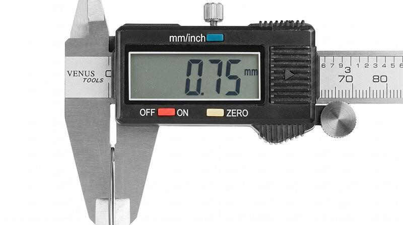
When a 0.7 mm probe barely fits a nominal 0.75 mm passage, small variations in geometry may trap or damage the probe.
Optical and Mechanical Selection Factors
Depth of Field
Ultra-thin inspection normally takes place at a very short working distance. The target may be only a few millimetres from the lens.
The probe's minimum focus distance must therefore match the internal diameter of the passage.
A probe may physically enter a small tube but still produce a blurred image if the wall is closer than the specified minimum working distance.
Field of View
A wide field of view helps with orientation but can make a small defect appear smaller in the image.
A narrower field of view provides greater apparent magnification but shows less surrounding geometry.
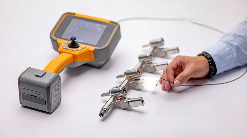
Viewing Direction
Front view is generally preferred for following a passage and inspecting surfaces ahead of the probe.
Side view is useful for inspecting the wall beside the probe, but it requires careful matching of:
Tube internal diameter
Lens working distance
Viewing angle
Available illumination
Illumination
Illumination becomes increasingly difficult as probe diameter decreases. Small probes have limited space for LEDs, light guides and heat management.
The target surface also affects the result:
Dark cast surfaces absorb light
Polished metal creates glare
Oil or fluid can cover the lens
Rough internal walls create strong shadows
Long probe configurations may provide less effective illumination
Probe Stiffness
A highly flexible probe can follow curved passages but may be difficult to push through a long straight tube.
A semi-rigid probe is easier to position but may not follow tight bends.
For repetitive production inspection, the ideal stiffness is often determined by testing the actual component.
Articulation
The smallest probes are normally non-articulating because there is not enough internal space for a camera, illumination, wiring and a steering mechanism.
Where directional control is required, possible solutions include:
Selecting a larger articulating probe
Using a pre-shaped guide tube
Rotating the component
Using a positioning fixture
Selecting a side-view optical configuration
Probe Length
Longer is not always better. Increasing length can make an ultra-thin probe harder to push, position and protect.
The recommended length is normally the shortest configuration that can reach the target with adequate handling allowance.
Outer Sheath and Durability
The probe may use metal braid, polymer, polyimide or another protective construction.
The appropriate sheath depends on:
Required flexibility
Surface condition inside the component
Expected inspection frequency
Exposure to chemicals or fluids
Repeated bending at the entrance point
Ultra-thin probes should not be dragged across sharp hole edges or repeatedly bent at the same transition point.
Typical Defects by Application
| Application | Possible Visual Indications | Important Additional Test |
|---|---|---|
| Turbine blade internal casting | Residual core, porosity, cracks, flash, burrs and blockage | Flow testing, radiography or CT where required |
| Film-cooling hole | Incomplete breakthrough, debris, burrs, chipped edges and coating intrusion | Airflow, geometric or calibrated hole inspection |
| Aerospace precision tube | Scratches, contamination, weld irregularity, deformation and blockage | Leak, pressure or dimensional testing |
| Additively manufactured passage | Loose powder, partially fused material, blockage and rough internal features | CT, flow or surface-characterisation methods |
| Pacemaker component | Foreign material, burrs, assembly misalignment and visible surface damage | Electrical, seal-integrity and validated functional tests |
| Catheter lumen | Blockage, debris, scratches, kink, bonding residue and local deformation | Flow, dimensional and cleanliness verification |
| Cannula or needle | Internal burrs, particles, side-hole damage and wall scratches | Dimensional, cleanliness and functional testing |
Recommended Inspection Workflow for High-Value Components
1. Define the Inspection Objective
Identify exactly what must be observed:
Entrance condition
Complete internal passage
Hole breakthrough
Internal wall
Cross-hole intersection
Weld or bonded area
Foreign material
2. Map the Complete Access Path
Record:
Minimum entrance diameter
Minimum internal diameter
Passage length
Number of bends
Bend radius
Steps or transitions
Expected target distance
3. Test a Representative Sample
Probe selection should ideally be verified on a real component, rejected sample, engineering mock-up or representative tube.
A drawing confirms nominal geometry but may not reveal burrs, internal roughness or the force required to advance the probe.
4. Establish a Repeatable Fixture
Production inspection becomes more reliable when the component and probe are positioned consistently.
Useful accessories may include:
Probe guide tubes
Insertion-depth stops
Component holders
Rotational fixtures
Linear slides
Inspection templates
5. Create Reference Images
Store approved examples of:
Acceptable surface condition
Known burrs
Blocked holes
Residual material
Weld irregularities
Contamination
Reference images reduce differences between operators and improve reporting consistency.
6. Control Lighting and Exposure
Maximum brightness is not always best. Reflective surfaces may require lower illumination or a different viewing angle.
7. Record Orientation
A defect image is useful only when its location can be identified.
Record the insertion depth, component orientation and viewing direction together with the image.
8. Inspect the Probe After Use
After each inspection or production batch:
Check the distal tip
Inspect the outer sheath
Look for permanent bends
Clean the lens
Confirm image quality
Store the probe without tight coils
Why the Smallest Probe Is Not Always the Best Choice
Selecting the smallest probe may appear to provide the greatest access flexibility, but an unnecessarily small probe can reduce inspection reliability.
Where the component permits it, a larger probe may provide:
Better image detail
Stronger illumination
Greater mechanical durability
Improved insertion control
More stable image capture
Additional viewing options
Articulation capability
For example, if both a 1.0 mm and a 1.8 mm probe can safely enter the complete passage, the 1.8 mm option may provide a more practical production solution.
The 0.7 mm or 1.0 mm probe should be selected when the smaller diameter is genuinely necessary.
Advantages of an Electronic Videoscope Compared with a Similar-Diameter Fiberscope
Historically, extremely small inspection diameters were often possible only with fibre-optic borescopes or fiberscopes.
With electronic videoscope probes now available down to approximately 0.7 mm, some applications can replace a similar-diameter fiberscope with a digital imaging solution.
The main advantages can include:
Direct digital image capture from the distal camera sensor
No visible honeycomb pattern from an imaging fibre bundle
No gradual loss of image points caused by broken imaging fibres
Easier image and video recording
More convenient file storage and inspection reporting
Digital zoom and image adjustment
Easier display on a larger monitor
More consistent image sharing between operators and quality departments
Simpler integration into production documentation
A fiberscope can still be useful where the absolute smallest possible diameter or a special optical arrangement is required.
However, when an electronic videoscope is available at the required diameter, it can provide a more practical digital workflow and a cleaner image for routine manufacturing inspection.
Practical Limitations of Ultra-Thin Videoscope Inspection
Limited Image Detail
Smaller probes contain smaller imaging components. A micro-probe may provide enough detail to confirm blockage or a burr but may not resolve a very fine crack.
Limited Illumination
Long, dark or highly absorptive passages may exceed the practical illumination capability of the probe.
Limited Directional Control
Non-articulating probes follow the available passage and cannot actively turn toward an adjacent feature.
Mechanical Fragility
Ultra-thin probes are more sensitive to crushing, twisting, pulling and repeated bending than conventional industrial probes.
Restricted Working Distance
The target may be outside the lens focus range even though the probe fits through the opening.
Visual Inspection Is Surface-Based
A videoscope can only show visible surfaces. It cannot reveal subsurface cracks, material composition or conditions hidden behind the observed wall.
No Automatic Pass-or-Fail Decision
Image capture alone does not establish acceptance. The manufacturer must define the defect criteria, inspection method and reporting requirements.
Frequently Asked Questions
What is the smallest available electronic videoscope probe?
Current ultra-thin electronic videoscope technology can provide probe diameters down to approximately 0.7 mm, depending on the required length, optical design, illumination and probe construction.
Can a 0.7 mm or 1 mm videoscope probe articulate?
Ultra-thin probes around 0.7 mm to 1.0 mm are normally non-articulating because there is insufficient internal space for the camera, illumination, wiring and steering mechanism.
Can an ultra-thin probe inspect turbine blade cooling holes?
Yes, when the hole diameter, path, working distance and probe configuration are compatible. The inspection may identify visible blockage, debris, burrs or incomplete breakthrough.
Can a videoscope verify the exact diameter of a cooling hole?
Not with a standard visual image alone. Exact diameter, angle and position require a suitable calibrated measurement or another validated inspection method.
Can ultra-thin probes inspect pacemaker components?
Ultra-thin probes can be used for suitable pacemaker components during manufacturing, before final sealing or where an accessible internal feature exists. They are not intended for use inside a patient.
Which probe is suitable for catheter lumen inspection?
The probe must be smaller than the minimum internal lumen diameter and must match the tube length, flexibility and bend radius. A straightening or positioning fixture may be required for flexible catheters.
Can an electronic videoscope replace a fiberscope?
In many applications, yes. When the electronic videoscope is available in the required diameter, it can provide direct digital imaging, easier recording and reporting, and no visible fibre-bundle pattern.
Can one ultra-thin probe cover every aerospace and medical application?
No. Applications vary in diameter, length, stiffness, viewing direction, focus range and illumination requirement. Several probe configurations may be required for different components.
Conclusion
Ultra-thin videoscope probes provide direct visual access to some of the most difficult inspection areas in aerospace and precision medical manufacturing.
Electronic videoscope probes are now available down to approximately 0.7 mm, enabling digital inspection in applications that previously depended mainly on fibre-optic borescopes.
In aircraft turbine blade production, ultra-thin probes can support inspection of investment-cast internal cavities, cooling passages, laser-drilled film-cooling holes and trailing-edge discharge features.
In medical-device manufacturing, they can be used for accessible pacemaker components, catheters, cannulas, needles, precision tubes and other miniature lumens.
Successful inspection requires more than choosing the smallest available diameter. The probe must match the complete access path, depth of field, viewing direction, illumination requirement, component material and required defect visibility.
For high-value components, the preferred approach is to test the inspection on a representative part, establish controlled positioning and define clear acceptance criteria before introducing the system into production.